What's News
- Lumousoft Inc. is specializing in graphic language design for embedded system. It has own compiler which is suitable for graphic and RTOS. Lumousoft graphic language is 100% module-based language even its library is built in module without the interaction of other language.
Free Download
- Lumousoft Splitwasher 2018 for PIC
And More
- Why Lumousoft
- Learning Center
- FAQs
- About Us
- Contact Us
-
Send us message
-
Tel: (519) 746-7178
-
Email: info@lumousoft.com
How to Start Lumousoft Splitwasher 2015 for PIC
Lumousoft Splitwasher 2015 for PIC enables the user to intuitively design or develop PIC embedded software in the environment of graphic blocks. Using DFG (Data flow graphic), CFG (Control flow graphic) and Lumousoft path analysis technology, this software program can avoid memory overlap that can cause unknown bugs as many other IDEs. Furthermore, it can fully recycle memory and perform reduction of program code.
A. Installation
- Download Lumousoft Splitwasher 2015 from http://Lumousoft.com or Click Download Lumousoft Splitwasher 2015 for PIC
- Install splitwaher 2015 ignoring antivirus software warning and allow installation
- When finishing installation, it will automatically run and pop up a dialog window to require creating project. The spiltwaher icon will be created on the desktop and the program is installed in the folder of program files(x86) with a folder named as Lumousoft Splitwasher 2015.
B. Layout
-
Place start, end and end loop blocks as fig. 1 shows. Click on menu Place >> Control Icon >> Start Icon, the start block will appear at the mouse and move the start block to the a place, left click the mouse right button, the start block will be placed. In the same way, the End icon blocked can be placed. Because start and end or end loop blocks are usually used once in a program, this is the only method to place theses blocks. The End Loop block might not be needed in a program.
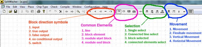
Fig.2 Tool Bar
-
To place other block element, as shown in fig.3, can be completed by left click on the element icon in the area of tool bar common Elements or click place menu. For instance, to place a block just click on block icon in the tool bar as shown in fig. 2 or the menu place>>Element. A block icon appears close to the mouse, move the mouse to the desired location, left click mouse button, the block is placed. if you want to continue to place more blocks you can left click and a new block will display and place by repeating previous steps . If you want to cancel new element placing, you can right click and then the element will disappear.
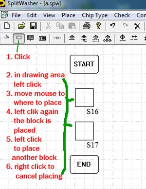
Fig.3 Place block
- To place other block element, as shown in fig.3, can be completed by left click on the element icon in the area of tool bar common Elements or click place menu. For instance, to place a block just click on block icon in the tool bar as shown in fig. 2 or the menu place>>Element. A block icon appears close to the mouse, move the mouse to the desired location, left click mouse button, the block is placed. if you want to continue to place more blocks you can left click and a new block will display and place by repeating previous steps . If you want to cancel new element placing, you can right click and then the element will disappear.
-
Draw line illustrated in fig. 4. Click tool bar drawing line icon, left click in the drawing area to start draw line, move down, right click or double left click to stop drawing line. When drawing line cross a block, a red cross symbol will show up at cross point. When start to draw a line from a line segment, left click and draw, a join dot will automatically show up at the cross section; when drawing line come across another line, a cross symbol will appear, if left or right click, a cross joined dot will display automatically. Notice that connected lines cannot be connected in a loop.
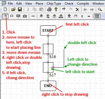
Fig.4 Draw line
- Place flowing direction symbol as shown in fig.5. Click on direction icon on the tool bar, and then click the red cross symbol on block boundary, the cross symbol will be changed to the selected symbol.
- Selection. Selection can be used to copy, delete and move. Click on one of selection icon in the tool bar, and then click on the target element, the selected element will change red in color. Block selection uses a block to select elements that enclosed by this block, fig.6 illustrates placing selecting block. The selecting block can be changed size and move by the user.
- Movement. When elements are selected, click on one of movement icons, the selected elements will move with mouse. If want to cancel movement, just right click. If want to move only selected elements, press shift key, the connected element which is not selected will keep stationary.
- Flexible dot as shown in fig.7: The flexible dot is used to break a line into two and we can handle each piece of line.
- Start line and end loop back (Fig.8) : Start line is the line connected to start block, End loop back line is the line connected to end loop back line. These two lines must keep independent, in other words, these line must come from the special block not from other source.
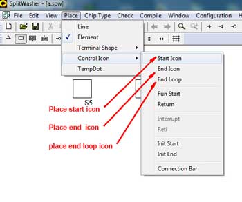
Fig.1 Place start and end block
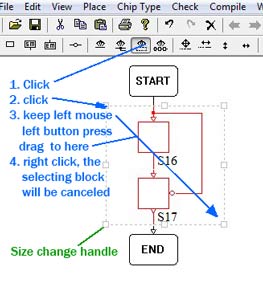
Fig.6 Selecting block
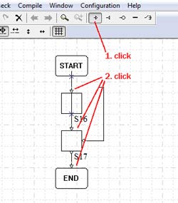
Fig.5 Place flow direction symbol
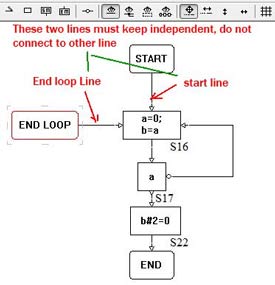
Fig.8 Start, end loop lines
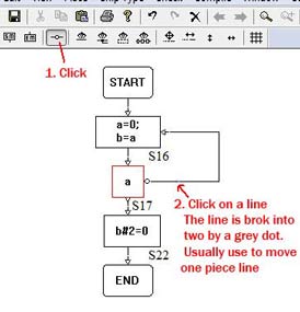
Fig.7 Place flexible dot
C. Coding
- Select chip type, click on the menu chip type and then select one chip that you want to work on.
- Fig. 9 shows how to code in a block. Click on the single select icon on the tool bar. Double click on a block, then a block dialog will pop up. You can write code in the coding area, each line is separated by semicolon.
-
Bit, pointer, point to point variable can be defined in the code if they are not defined in the variable manager dialog.
- Bit: a=&(b#2), the variable a will be treated as a bit variable.
- Pointer: if a=&b; c=a, a and c will be considered as point variable. if *a[index1,index2,…] appear in code, the array a will be seen as pointer array.
- point to point variable: if **a appear in the code, a will be seen as point to point variable, if a is point to point variable, c=a in codes variable c will also act as point to point variable.
- Array dimension can be redefined in code. For example dim a[2,2], where dim is key word to define array dimension. Array is implemented in the format of a[index1,index2,…], different from c language method like a[index1][index2]..;
- Constant value can be redefined repeatedly in the code. For instance, we first define constant a=2, later we can define a=5
-
Data type:
- char and unsigned char -1 byte(8 bit);
- short and unsigned short -2 bytes(16 bit);
- int and unsigned int -4 bytes(32 bit);
- long and unsigned long -8 bytes(64bit);
- float is fixed float point, but Lumousoft offers flexible fixed float point, namely, the user can define total byte used for float point and how many bits used for point fractions.
- Bit type variable: the variable is referred to one bit located in non-bit and non-float variable. In code we can define as: bitVar = &(var # bitPosition), or var # bitPosition to represent a bit variable.
- Void is for module variable when the module does not return any value.
- Variable Scope. Local, Weak global, Global, Constant, System, State, My System
-
- Local: The variables can only be used in the connected blocks or one modules
- Weak Global: The variable can be used in all modules in the same page or the same file. Other file cannot use it.
-
Global: The variable can be used in all modules in the all files or pages in the same project . As for other files, the files must be included in the sub files. The sub files must be built before it exports its global variable for the project using. Fig.10 shows how to involve other file’s global variable.
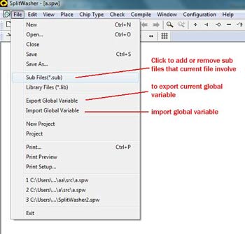
Fig.10 Global variables in Project
- Constant: as name imply, it is can be used in all files like global variable
- System Variable: system register variable, the initial value can be edited in variable manager dialog
- My system Variable: It allows the user to rename the name of system bit variable. For instance RA0 (PORT A bit0) can be renamed as LED0 in my system variable.
- State: reserved for Lumousoft further development
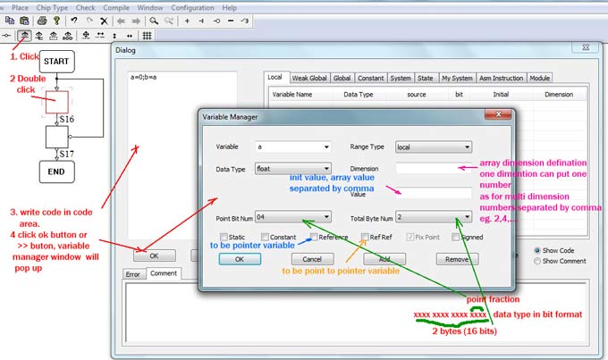
Fig.9 Coding diaglog
D. Module (function)
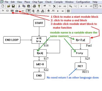
Fig.11 Module
Inline and regular module can be in different files. In Lumousoft software, the module name itself is a variable, all module variables in the same tread share the same memory, therefore, there is no need for return statement as other textual language does. Fig.11 shows how to place a module. As c language, Lumousoft allows module function parameter having default value, the default parameter can be located in any place not like they must be put rear place . For example f(z=2,x,y),f1(z,x=2,y=1),when this module is called and use the default parameter, we can call in the format f(,b,c); f1(z);
E. Memory optimization
Lumousoft path analysis technology can fully recycle memory and reduce code. Each local variable’s life-time can be determined by this technique. Therefore, a local variable with the same name in different life period might has different physical address. For example a=b;… a=c , variable a has two different life, the physical address assigned to variable a might be different. Furthermore, for local variable assignment like a=b; if b is not longer live or it is dead at this statement a=b; while variable a need a new physical address to map to , if we assign b physical address to a, obviouly we do not need any code to perform assignment, the assignment code can be reduced. In the result asm file generated by compiler, we can see the sign “ <=> ” which means the variables on the both side has the same identical address, and the assignment is reduced.
F. Output file
After building (compile>>build on the menu), if success it will generate four files in the folder of out\result in the project working location. Asm, h, hex and memory usage report files. Another file in the folder of out\flow in the project working location also is given to show how the compiler define program flow, this file with extension flw can be open by any plain text reviewer.
If the file does not contain start and end block, but contain modules click the compile>>build on the menu, it will generate intermediate file in sub folder, and this file are used for other files to include.