What's News
- Lumousoft Inc. is specializing in graphic language design for embedded system. It has own compiler which is suitable for graphic and RTOS. Lumousoft graphic language is 100% module-based language even its library is built in module without the interaction of other language.
Free Download
- Lumousoft Splitwasher 2018 for PIC
And More
- Why Lumousoft
- Learning Center
- FAQs
- About Us
- Contact Us
-
Send us message
-
Tel: (519) 746-7178
-
Email: info@lumousoft.com
Lumousoft graphic language construction
1. Basic Units
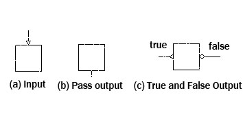
Figure 1 directions
Lumousoft software product is based on graphic modular mechanism to generate machine codes from graphics. Lumousoft GMIDE graphic module is basically made of four units: block, line ,direction and statements in the block. Blocks contain executable statement codes which perform logic and arithmetic operation; line is applied for building connection between blocks; direction determines how the process flows. The symbol of direction is shown in figure 1. There are two class directions, input and output. The output can be further divided as non- conditional output (pass output) and condition outputs (true and false output).
2. Modules
Lumousft graphic language program consists of 5 parts: main process module, library, sub module, global initialization and interruption modules.
- Main process module: It is similar to “main” function in c language, as shown in figure 2(a).
- Library: support compilation for logical and arithmetical operation
- Interruption: to handle interruption routine for microprocessor, as shown in figure 2(b)
- Sub module: it is similar to the function in c language and can be used by other module. Sub modules can exist in different files. Sub module can be either module function or inline module as shown in figure 2 (d) and (e).
- Global initialization: It is used to initialize global, system and static variable and perform microprocessor initialization before running main program module as shown in figure2 ( c )
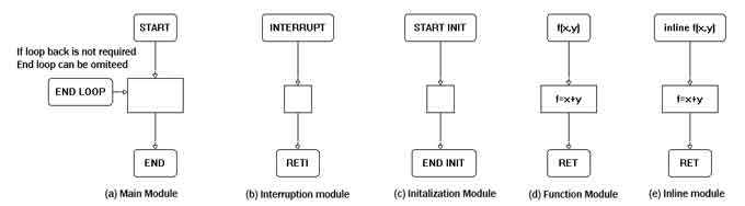
Figure 2 Modules
The whole structure is illustrated in Figure 3 Structure Map.
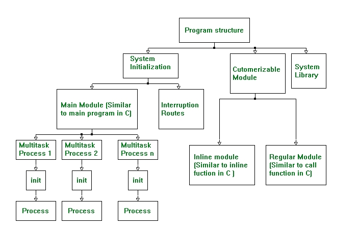
Figure 3 Structure Map
3. Operation
The statement in the block can perform the following operations:
- Arithmetic: +, -, *, /, %
- Assignment: =
- Augmented assignment: +=, -=, *=, /=, %=, &=, |=, ^=, <<=, >>=
- Bitwise logic: ~, &, |, ^
- Bitwise shifts: <<, >>
- Boolean logic: !, &&, ||
- Equality testing: ==, !=
- Sub module: ( )
- Increment and decrement: ++, --
- Order relations: <, <=, >, >=
- Reference and dereference: &, *, [ ]
- Conditional evaluation: ? :
- Bit: #
Statements in block is used for logical and arithmetical operation, it can be expressed in logical or arithmetical expression or directly in assembly language, the operator of variable used in assembly language can be the same as that used in expression .
4. Layout format
The block diagram can be layout in the form of series, parallel, bridges, loop to form complicated network. Figure 3 illustrates the basic layout format.
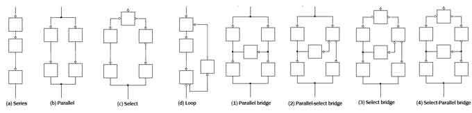
Figure 4 basic Layout format
5. Variable
5.1 Scope — The variable can be local, weak global, global, system and mystem according to the scope of application.
- Local : local variable is defined in a module, and cannot be used by other module. Local variables are fully recycled
- Weak Global: The variable can be used in the modules in the same page, the modules of other page cannot use.
- Global: The variable can be used in all modules in the poject
- System: The special registers defined by sytem can be used by all modules in the poject
- Mystsem : The bit name of Ststem variable is defined by customer, can be used by all the modules in the same page.
5.2 Data type — char(1 byte), short(2 bytes), int(4 bytes), long(8 bytes), unsigned char( byte), unsigned short( 2 byte), unsigned int(4 bytes), unsigned long (8 bytes), bit
Bit variable does not exist in many languages. Bit variable has source variable and bit position. Bit variable refer to a bit of the source variable and it has either ‘ 1 ’ or ‘ 0 ’ value. Bit variable can be defined in variable manager diagram or in the code statements defined as the expression “ bit=&(Var # bit_position) ” or “ var # bit_position ” to stand for the bit of var, where var indicated a source variable, bit_position is the location where the bit sit in the source variable. The bit variable could be treated as Boolean.
5.3 Other type — Constant, static, array, similar to c language
Variable does not need declaration , when the variable is defined any where in a module, it can be seen within the whole scope that it stays.
5.4 Memory Optimization
The memories assigned by local variable except static variable are fully recycled. The graphic compiler can statically analyze the path of process and indentify when the memory alive and dead. When the variable is assigned, the memory associated with the variable is born, when it is last read, it is dead and the memory assigned by the dead variable is released and can be used by other variable. Therefore, the variable might has different memory address along the process flow path depending on the how many times the variable live and die.
5.5 Constant and Array Dimension
Constant can be assigned different constant value along the process flow path as long as there is not conflict. The conflict arises when the constant come from different flow paths and in the different path it is assigned by different constant value.
Similar to the constant, the dimension of array can be changed and the memory associated with the array is changed too. If dimension of an array is reduced, the memory associated with the cut off array is no longer needed will be released and can be used by other variable.
6. Multiple Files
6.1 library files — Here library files are applied to transfer customer designed original files into intermediate files, the library files has extent name “ lib ”. When chip type is selected the relevant library will be automatically included.
6.2 Sub files — Sub files is created by customer, usually the sub file contain function modules and inline modules, these files need to be build as an object file with extent name “ sub ”, If the other file need to implement the modules function and inline modules these sub object files needed to be included. With sub file, multiple page of graphic codes can be used, easy for team work and reusable code.